
A step by step guide to drawing a building
Congratulations on completing your measured survey! Now it is necessary to produce finished drawings.
Equipment required:
- Drawing board
- Tee square
- Steel ruler / straight edge
- Scale ruler
- Set square
- Compasses
- Pencils and drawing pens (and erasers!)
- Paper
- Tracing film
- Masking tape
Suggested scales and drawing conventions:
Plans, sections and elevations:
- Small domestic buildings 1:50
- Medium buildings e.g. church 1:100
- Large industrial buildings 1:200
Roof sections are usually drawn at a scale of 1:50
Most building drawings follow English Heritage (EH) guidelines (see reference at the end of this paper). You should refer to these as you draw. Level 2 conventions are adequate for most non-professional purposes.
Procedure for plan drawings:
- Begin by drawing on paper, secured to the drawing board with masking tape.
- Draw a baseline parallel to the bottom edge of the paper, set square to the vertical edge. This will be the outer edge of your first wall. It is usual to begin with the front elevation wall.
- Draw a second line parallel to the first, establishing the length and thickness of the wall. This will be your inner wall.
- Now, starting at the front door, move along the inner face of the front wall, in each direction, marking in windows, doors and masonry breaks. Remember that windows are normally wider inside than out! Use the EH conventions for features such as windows, doors, stairs etc.
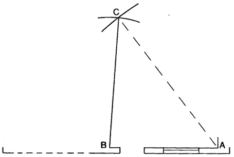
- Having completed the front wall, it is necessary to establish the shape of the first room. If you believe the room is square, then you can complete it using a set square for the right angles. If it is not square, you must use your diagonal measurements and a pair of compasses as follows:
- Place one end of the compasses at one corner of your first wall (point A)
- Open the compasses to the scale distance of one diagonal measurement
- Make an arc on the paper at this distance from point A
- Now repeat this process from the other end of the first wall (point B), marking another arc (point C). This marks the corner of the third wall
- Repeat the whole process with the other diagonal measurement to find the corner of the fourth wall
- Now the other walls can be drawn in
- A few notes about drawing conventions:
- Overhead features in a room, such as beams, are shown in a broken line
- It is not necessary to draw in all overhead features, such as all of the ceiling joists. These can be represented with a single notation (see EH guide)
- Stairs are drawn rising to waist height only, with an arrow to indicate the up or down (depending on which floor you are drawing)
- Doors are often just left as openings, but there are special notations for windows. Consult the EH book.
- Timbers cut through in a section drawing are shown in black, as they are coming towards you
- Fireplaces are initialled with f
- Now complete this same procedure for all the ground floor rooms
- If drawing an upper floor, it is usually possible to use the overall measurements from the ground floor, adding in variations and upper floor features.
- Label each room with a letter and number, such as G1 for ground floor room 1. Don’t use functional labels, such as kitchen
Remember to keep the drawing simple and uncluttered with minimal labelling.
Procedure for elevation drawings:
Decide which elevations are the most useful; you might only draw one or two, rather than all four.
- Work from either the eaves line or an artificial baseline if you have measured from the latter
- Check whether window tops are in line; don’t assume that they are!
- An elevation is drawn face on, with all features depicted as flat
- If drawing more than one elevation, make sure that each corner of the building is the same height in your drawing
- You can convey the roof covering material somewhat stylistically; e.g. wavy lines for pantiles, but only in a small part of the drawing, rather than across the whole roof
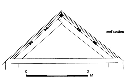
Other drawn features;
-
You may wish to include a drawing of a
section through the roof, as described in the measuring guide.
This will look something like this when complete:
- It might also be useful to draw significant features, such as an unusual door or fireplace. These should be drawn at 1:50 or even 1:20
Preparing the final drawing:
- Where possible, arrange all the drawings on a single sheet
- If there are elevations and plans, place the ground floor plan to the bottom left of the page, with other plans to the right of it. Place the front elevation drawing above the ground floor plan
- Always include:
- A north arrow
- A scale bar and a note of the scales employed (e.g. 1:50)
- The name of the building and any reference numbers
- The names of the surveying team
- The survey date
- Double check all measurements with your rough sketch before you finish
- Now place tracing film over the drawing and make an ink copy, using a fine drawing pen and bevelled ruler
- Remember that ink takes a while to dry, so be careful not to rub your hand or ruler over wet ink or it will smudge!
What to do with the drawings:
The drawings should now be attached to a written report (see separate guide to writing the report) and copied. It is helpful to give copies to the following parties:
- The householder
- The HER (Heritage Environment Record) based at the County Archaeological Service office
- The Centre for Buckinghamshire Studies
- The Buckinghamshire Archaeological Society library (at the County Museum)
Consider also the possibility of publishing the results in a local, county or national journal, particularly if the building is of special significance, or forms part of a larger study.
References:
Hutton, B. 1986. Recording Standing Buildings. The British Archaeological Trust
Swallow P, Dallas R, Jackson S and Watt D. 2004 (2nd edition) Measurement and Recording of Historic Buildings. Shaftesbury: Donhead Publishing.
Understanding Historic Buildings: a guide to good recording practice. Swindon: English Heritage (2006)
Sue Fox
November 2009